OpenUtilities Substation Help

Device Cross Referencing Dialog

This dialog enables you to configure the format of your device cross references. You have the ability to control the layout, positioning, content, and display of the cross references. There are tabs near the top of this dialog to select between layout for the cross reference and format (content) of the cross reference.

Accessed when the Edit button is pressed from one of the Device Cross Reference field in the Options > Display Formats page.

Note: Cross reference positions set in this dialog do not take priority over cross reference position set during symbol creation.
Note: When you have made the desired changes to the device cross reference format, use the Save Profile button to save the changes for all future projects using the profile. If you select the OK button (without saving) the changes will only apply to the current project.

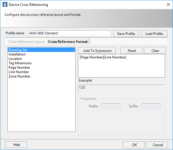
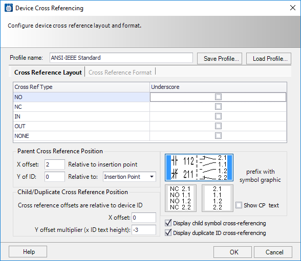
Cross Reference Layout Tab

These option settings allow you to configure the general layout and positioning of cross reference text as well as some display preferences.
SettingDescription
Profile Name The name of the current device cross reference profile. The profile is a saved format that contains all your settings from this dialog. You can create new profiles, save them and reload them as your project needs require.
Save Profile Saves changes to the current profile. If desired, you can change the entry in the Profile Name field and save the changed profile under a different name.
Load Profile Loads a previously saved profile.
Cross Ref Type

In the Cross Ref Type column, various types of devices are listed: NO (Normally Open), NC (Normally Closed), IN (Input), OUT (Output) and None (no cross reference prefix).

You can select whether or not cross references for each type of device will appear on the drawing with an underscore. Select the Underscore check box for each cross ref type that you wish to be underlined.

Note: The cross ref type for each symbol is defined by the cross reference prefix text that is chosen when the symbol is created.
Parent Cross Reference Position

Enter coordinates to determine the position of the cross reference.

  • X Offset - Specifies the X offset that the cross reference symbol will be placed at relative to the insertion point of the parent symbol.
  • Y Offset - Specifies the Y offset that the cross reference symbol will be placed at relative to the insertion point of the parent symbol or to the origin (0) of the drawing depending upon which choice you select from the Relative to pull-down list. The first choice is more commonly used in ANSI/JIC drawings and the second is typically used in IEC drawings.
Note: These settings use the units of measure you specified in the Default Units of Measure setting in the Project Options > Drawing Standards dialog.
Note: These settings are overridden by the offset settings specified in a family definition. You can also specify a cross reference symbol position for the parent symbol in symbol creation which takes precedence over all other settings.
Child/Duplicate Cross Reference Position

Sets the position of cross reference text that appears at child or duplicated symbols.

  • X Offset - Specifies the X offset that the cross reference text will be placed at relative to the device ID position on the symbol.
  • Y Offset Multiplier - Specifies the Y offset that the cross reference text will be placed at relative to the device ID position on the symbol. The value you enter will be multiplied by the ID text height to yield the Y offset value that gets applied. Negative numbers can be entered to make the cross reference text appear below the ID.
Note: These settings use the units of measure you specified in the Default Units of Measure setting in the Project Options > Drawing Standards dialog.
Note: In symbol creation you can place a cross reference attribute to define the position for the cross reference text which will take precedence over these settings.
Display Child Symbol Cross-referencing

There are several examples of graphic presentations of the cross reference in the dialog. You can click on the style that you prefer to select it.

  • Show CP Text - Select this check box if you wish the connection point text of the cross-referenced symbol to be included.

Cross Reference Format Tab

SettingDescription
Profile Name The name of the current device cross reference profile. The profile is a saved format that contains all your settings from this dialog. You can create new profiles, save them and reload them as your project needs require.
Save Profile Saves changes to the current profile. If desired, you can change the entry in the Profile Name field and save the changed profile under a different name.
Load Profile Loads a previously saved profile.
Available Elements Lists the available elements that can be added to the cross reference.
Add to Expression To add an element, select it, and then click the Add to Expression button. It will then be shown on the right side of the dialog as part of the cross reference.
Currently Selected Elements The right side of the dialog displays the currently selected cross reference elements.
Remove Elements To remove an element from the cross reference, select it, then either press the <Delete> key or right click on the element and select Delete from the menu.
Reset Reloads the combination of elements that you had when you entered the dialog.
Clear Empties the field of all selected elements.
Prefix/Suffix The Prefix and Suffix fields allow you to define a character string that will be placed at the beginning (Prefix) or end (Suffix) of the cross reference element. These fields are active only when one of the cross reference elements is selected.

The Width and Fill with fields allow you to set the number and type of characters that will be used for the selected element. These fields appear when you select a tag element and then select the Fixed number of characters check box.

Note: If you do not select this check box the software will use as many characters as necessary for a given value.

The entry in the Width field sets the number of digits that will be used for the value (more will be used if necessary). The Fill with field defines the character that will be used if necessary to fill out the value to match the width value.

For example: Page Number set to Width 3, Fill with 0. Cross references to devices on page 2 will use the value 002. Cross references to devices on page 13 will use the value 013. Cross references to devices on page 3333 will use the value 3333.

Save Profile Saves the changes for all future projects using the profile.